 |
||
        |
Detailled Design of the PipePump
Given the utter simplicity and excellent dirt handling of the rest of the PipePump, something simpler and less dirt trapping than the ordinary multipart piston valve and seal was sought. Dirt settling out of the water column can easily fill the space between the (leather) cup seal and the valve body and lock the cup seal at full upstroke contact, wear and friction. Also the conventional central valve flow from below is not a natural match for the new geometry or its rearrangements. The observation that the direction of the seal frictional force was same as the disposition of the valve lead to the idea of a single part valve and seal.
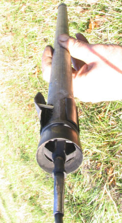
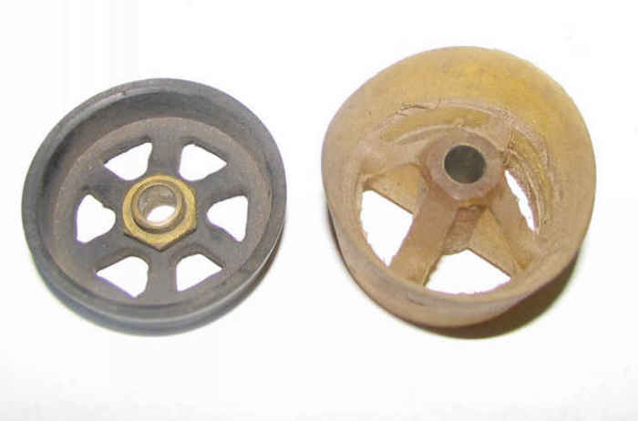
The top end of the shuttle is faced and turned to be a bit more than half the area of watercolumn and the center is tapped to receive all the short thread at the end of a long round rolled swage on the end of the pump cable. The valve seal is like a spoked wheel in plan with a long central bushing that can slide on the plain part of the swage. The 'rim' overlaps the edge of the top of the shuttle. The outside of the rim flares and thins upward to form a glancing upwards seal against the inside of the cylinder. There is no cavity where settling dirt can accumulate.
On the upstroke friction as well as pressure holds the part sealed against the top of the plunger and against the inside of the cylinder. When the shuttle motion reverses the part sticks to the cylinder wall until it has slid up the swage to its top end and openned the radial inwards and upwards passageway for water around the shuttle top.
This seal/valve single part can be cast elastomerically for instance with Por-a-Mold PolyUrethane Casting Rubber by Synair. Two sizes of aluminum mold were made and various prototypes cast . One had powdered graphite added to mimimise the friction and wear on the cylinder wall. Another was left in a fish tank for over a year with no effect on the heath of the exotic fish or visible deterioration under water.
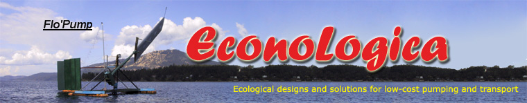
As illustrated in the photos below, this part can also be handmade from a commercially available cup seal and 1/8 pipe parts..
Bicycle inner tube rubber is suitable for the butterfly valve. The holes are best drilled through a template rolled to the pipe diameter out of perforated sheet found available from the cases of VCR's etc. At the other end of the plunger is a brass or plastic endcap holding the bearing seal and providing a good bevelled lead-in for the footpipe. The shuttle body is just a piece of pipe and the SS or bronze shuttle top is force fit into the end up to a top lip, after the static leather has been glued to the inside. Leather makes the best static seal because it tends to swell at any points lacking contact.
The footpipe is best made from brass, bronze,copper or SS pipe straighter and more stable than plastic with a thinner wall and bigger ID for less flow constriction and friction through the footpipe. The top should match the shuttle hole bevel bevel for to guide the shuttle over it.
The cylinder can be PVC pipe that is inserted into the bottom of the polethylene drop pipe and then glued/sealed there with elastomeric construction adhesive as well as clamped with several SS hose clamps. The upper end of the drop or rising pipe must be able to pass and not catch the lip of the shuttle valve seal as it is pulled up. This requires a bevel to be turned or ground on the inside of as a big an ID metal ring insert as can be obtainned and can be forced into the pipe. Construction adhesive should be used to lubricate and glue the assembly and many hose clamps should be applied to clamp the entire length of the insert..
See the prices page for a materials list for everything beyond the plunger .
Static sealing the pipepump for windmills
In unattended applications such as windmill pumping, the leather at the static bottom of the stroke with no wire tension would be pounded at the bottom of dynamic stroke as the wire stretches.This will likely cause leaking of the water column which not only reduces the net pumping in intermiitent wind, it also can so reduce the hydraulic return that the Wing'd Mill may overswing and have to latch if the wind suddenly arises. Bottom damping the plungers final descent cannot avoid some contact at moderate amlplitude. Also it is very difficult to get sufficient linear viscous damping with the water and not quadratic Bernoulli damping
Springing of the leather seat under the shuttle top to the static load still means water hammering when it shuts off the downflow. And on the beginnining of upward movement of the shuttle the reverse increase of internal volume between it and the still sealed footpipe can cause suction to the point of cavitation without unseating it. These problems require the inclusion of aircells as well as the spring behind the leather, that can absorb these volume changes whilst the footpipe is sealed. These can be the vinyl cells found on some sailing lifevests.
Likewise the suction in the upstroke behind a closel seal valve will not open the sprung footseal but only cause cavitation and its damage. Very fortuitously this can be avoided by allowing a large (lost) motion to our valve/seal so it does not close for the maximum stroke of the static seal spring which must equal the worst pump wire stretch.