|
|
DIY
FRONT ROWING
RIG (click for VIDEO)
|
Much faster & longer range solo canoeing Much straighter than solo paddle or std. row Watch where you’re going & avoid collisions Row straight there or explore ahead Oars automatically feather on return stroke 16’ Canoe speeds can reach 8 mph burst |
|
- Legs-only rowing
allows taking video : waving; holding charts, binoculars; jig fishing etc.
- Arms pull against legs pushing for whole body exercise. Dead weight of
oars and legs supported
- Simpler and more compact than the FrontRower:
-1 pair of
major springs easy to make vs 2 pairs with difficult ends
-1 pair of pulleys vs 3 on the Front
Rower
-ball bearings for twist also roll to sweep the oar
-Simplified lighter aluminum frame with wood seat snaps in and out of
canoe
-Simple one piece foot
pedals. Light adjustable seat belt supports back
-Generally far fewer moving parts and lighter at 15 lbs total
-Simpler lighter handles allow most
comfortable pulling position
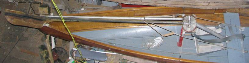
Prototype
Composite Oar
CLICK
for photo
of end view of pedestal
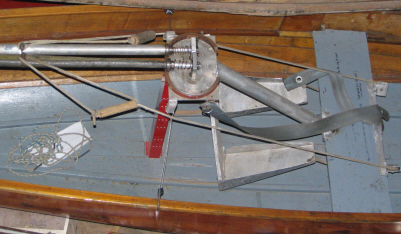
DESCRIPTION and MOTION
The oar
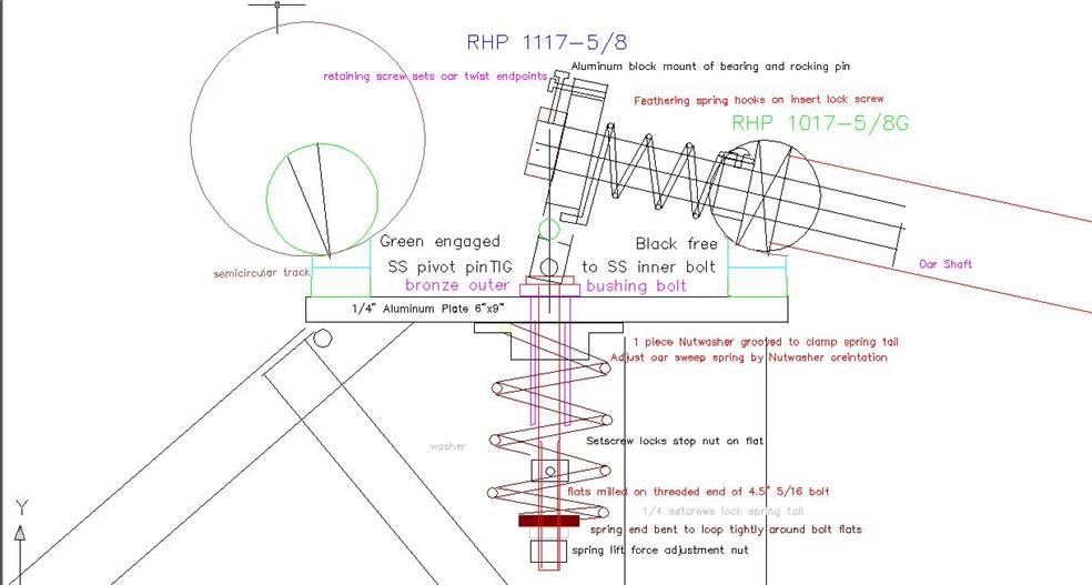
ends in a bearing in an alumimun block with a SS pivot pin through the bottom,
cutout in the middle where it is TIG welded in situ to the head of a long SS
bolt with its opposite threaded end milled to have side flats. The bolt and so
the bearing can rotate through a bronze machine screw sandwiching the pedestal
plate as well as slide up and down. A helical spring with one straight tail
clamped in the washer nut on the bronze machine screw, and the other tail formed to grip the flats of the bolt, spring loads the bolt and oar end down, and the oar forward. A setscrewed nut and washer set the vertical
travel and a nut below compresses the spring to set the lifting force.
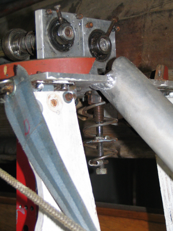
About 3
inches outboard, a
pillow bearing insert rotates around the
oarshaft and its radiused
outside rolls on a steel track. It and the springloaded inner bearing support
the weight of the oar whilst allowing it to sweep depressed or lifted, and to
feather on its own axis. Feather stops on top of the inner bearing block limit
the extended setscrew of the inner bearing. Between the bearing block and the
outer bearing setscrew and around the oar is a light secondary spring (with
bent ends) which biases the oar towards feathered. The feathered limit is say 5° to
horizontal to ensure the lifted blade skips in any water contact and lifts in
the apparent wind. The tripped limit is the blade angled to vertical aft to
drive it down in the water, so the net blade turn is about 70°.
The ideal rocking point is at the same height as the track surface so
there is no in and out movement of the rolling wheel on the track just a change
in contact between its convex radius and the track’s greater concave radius. To
achieve this height match to the SS pivot pin and prevent wear a very short
6”XH steel pipe cutting is machined to the angle and radius and then split for
the two sides and tapped to receive machine screws through the pedestal plate. The foot
pedals hinges are tapped into the aft underside back of the pedestal plate
At 20.5”
outboard the rope wraps around the oar shaft, so the jerk from the seat pulley
unfeathers as well as lowers the oars to catch. This jerk is natural at the end
of the oar return as the slack comes out of the ropes. Once caught the blade
inclination to vertical drives the blade down into the water to a few inches
immersion as set by the limit on the mainspring compression. When the rope pull
from the arms and legs stops at the end of the sweep, the oar springs out of
the water to drain and then slowly feathers to clear the water on its return
and reduce the wind resistance. The oar’s emergence is aided by tilting the
pedestal forward about 5 deg relative to the waterline.
The oar
blades are curved shaftwise and angled so that they skip on any incidental
water contact on the return and lift in the headwind. Their edges should be
parallel to the water on entry and immersion to minimise the travel required.
For light rowing or at the finish of the stroke the top of the blades needn’t
be immersed and there is no loss by flow over the top, but for the beginning of
strong strokes the tops have to be immersed a few inches to prevent ventilation
destroying any suction behind the blades. The hatchet shape is close to ideal
and suggests composite shafts for the tapering, changes of section, and for a
very low tip weight to lift. In any case it is practically very important that
the blade ends do not leak any water into the oar shafts.
SPECIFICATIONS
Main springs: port left handed, starboard right handed approx
pitch of .142” music wire wound on ¾”
pipe mandrel 4 turns at about ½” pitch
finished OD about 1.7” Twist spring wire
Feathering springs: port left handed,
starboard right handed 6 turns .075” music wire OD about 1”
“rolling”
Bearings: RHP 1017-5/8G radiused Insert only for 5/8” pillow block $8x2
end insert bearing RHP 1117-5/8 $10x2
Oar Length 7.5’ Blades Average Depth 7.5” , Length
18 “,
DESIGN HISTORY of
ROWRIG for CANUDA PLY
A canoe hull
is suitable for open water fast rowing because unlike a shell it can have
static stability with a rowing rig and has sufficient freeboard for rowing against any
waves that may spring up. Its fineness and stability put it in between a shell
and a Whitehall dinghy. Since sliding seats are used in some Whitehalls and all
shells, they are appropriate for the intermediate canoe.
One drop-in
sliding seat rig attaches to a canoe’s gunnels but weighs 50 lbs, as much as
the canoe. The shorter waterline and recurved ends of the canoe vs. the shell
will exacerbate the oscillation of pitch
and surge as the rower slides, which
loses energy to radiative wave damping as well as increasing the average of the
quartic drag near the ‘hump’. The
rower’s feet push the boat back as he ends his recoil and begins a new forward
slide, slowing the boat even more at its slowest point. Likewise at the end of
the stroke his deceleration exacerbates the peaking of the hull speed against
the wave drag hump.
I conceived
of a sliding feet alternative where the seat and the rowers
cg is fixed and his feet and the oarlocks slide instead. A web search found http://www.rowvirusboats.com/virus/sliding_rigger.html
with this idea in a production shell. That site gives the history of the
sliding wing rig back to the 19th century, and its
banning by FISA when it indeed proved more efficient in racing in the
1980’s.The site animation shows the sliding feet driving the oarlocks back as
the arms swing the oars about them. Thus in a final advantage Virus do not
themselves recognise, the blade’s
velocity relative to the boat is increased, so the oars can be shortened. For
example with 8’ oars 6’ beyond the oarlock swung through 60 deg the stroke
relative to the boat of normally 6’
is increased to 7.5’ with a scull’s
18” slide.
A review
of the classic rowing motion shows that the main muscle duties are legs push
open by 1.5’ and lock, arms lock and flex by 1.5’, and finally the back hold
for these 3’ strokes and rotate for
another 2.5’. The strain on the back is out of all proportion to its
normal use in the body and explains why
back injury is the overwhelmingly predominant injury amongst rowers. Muscle
mass and comparative studies between leg and hand cranking on bicycles show the
legs are capable of about twice the
muscle power of the arms.
By raising the seat and
lowering the feet and having the stretcher pivot, the (foot) slide can be
easily raised to 24”. Then the hand grips of the oars needn’t move fore and aft
(see the return stroke of the Virus animation) and can be tied to the bow, as
well as elastically counterbalanced to the floor of the canoe. This saves arm
and back static muscle energy consumption on long distances; the arms only have
to twist and lower the oars during the leg stroke which reacts against the
weight on the seat as in cycling. (The Ro-Cat
http://www.rocat.co.uk/boat/rigger.htm exploits the lack of movement of the oar end in its slider
geometry but still has the hand and back muscles statically restraining the
end, consuming muscle power but doing no useful work.)
At the
end of the leg stroke, the arms and back can still be used to unload
the wire for extra sweep and especially
to steer. (The angle of such one-sided arm strokes doesn’t reduce its yaw
torque about amidships). Then the foot
movement is 2’ multiplied by 4:1 to give
8’ of blade movement whereas the arm
movement is 1.5’ max applied 3:1 for a blade movement of 4.5’, roughly ½ as required. In sprints, like on a
bike, arm pull also serves to brace the body against the extra leg force beyond what the seat can restrain.
But with
this evolution of the foot rowing concept to include cables restraining and
counterbalancing the oars at the inboard end, it is just a reversal of the
inboard end pivots and cables pulling
the ‘rowlock’ in http://www.frontrower.com . Ron Rantilla has so outraced sliding seats
with the same hull. His has the obvious advantages of seeing where one is
going, and only pivoting not linear
motions. The lack of overhanging riggers and the oars moving independently
movable very high makes docking much easier. Not least it alone can be rowed
hands-free or with
armpower throughout the stroke.
So it was decided to customise, lighten and if possible simplify this
system for the Canuda Ply.
The
frame was triangulated by a strut from the pedestal to the seat between the
legs, and by side stays from the pedestal to snap over the gunnels of the canoe
with a compression strut to the keel.The feathering
motion was made external and to use a
bearing in common with the sweeping motion. The oar lift and return springs
were combined by using easy to wind helical springs with straight ends clamped
in the pedestal and in bottom spring blocks, eliminating the return lines,
pulleys and springs. A simple seat belt from the pedestal looped around the
back provides comfortable adjustable back support.Another
pair of pulleys was eliminated from the leg drive, and a pair of moving parts
and pivots from the leg levers.